Yosys Circuit Diagrams
NOTE: Multiple top-level design modules are not supported by Yosys Cicruit Diagrams.
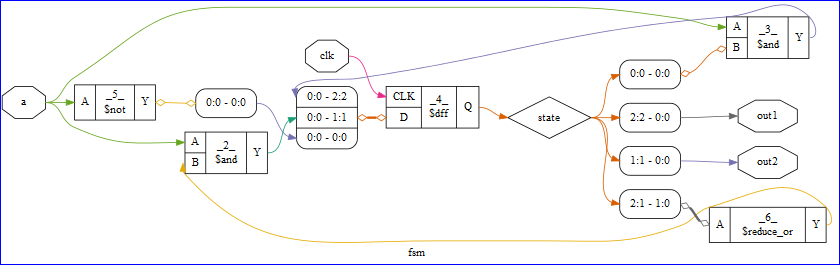
The Yosys synthesis flow can create circuit diagrams.
Square boxes are cells. Outputs on the right, inputs and unrecognized ports on the left. The first line of text in the box in the cell name, or _<number>_ for internal cells. The 2nd line is the cell type. Internal cell types start with a dollar sign. (There is a chapter in the manual about the internal cell library used in yosys.)
Diamond-shaped nodes are wires that are not ports. Octagon-shaped nodes are ports.
Elliptical nodes are constant drivers. The label has the format <width>’<bits> or simply <number> for 32 bit integers.
Boxes with round corners with lines such as 0:0 - 42:42 are used to break out and re-combine nets from busses. So for example
wire [3:0] a, b;
wire [7:0] y = {a,b};
will create the following box:
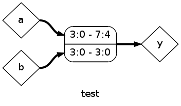
The numbers tell you which bits on which side are connected. for example ‘3:0 - 7:4’ means that the bits 3:0 from the left net are connected to bits 7:4 from the right net. Usually the box has a single connection on one side and individual connections on the other side. When such boxes are connected to each other or to a cell port, the connections have little diamonds on the ends instead of arrows. That’s because its not an actual connection in the sense of the internal RTLIL netlist format.
For a detailed explanation, see Yosys Application Note 011: Interactive Design Investigation